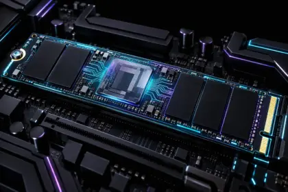


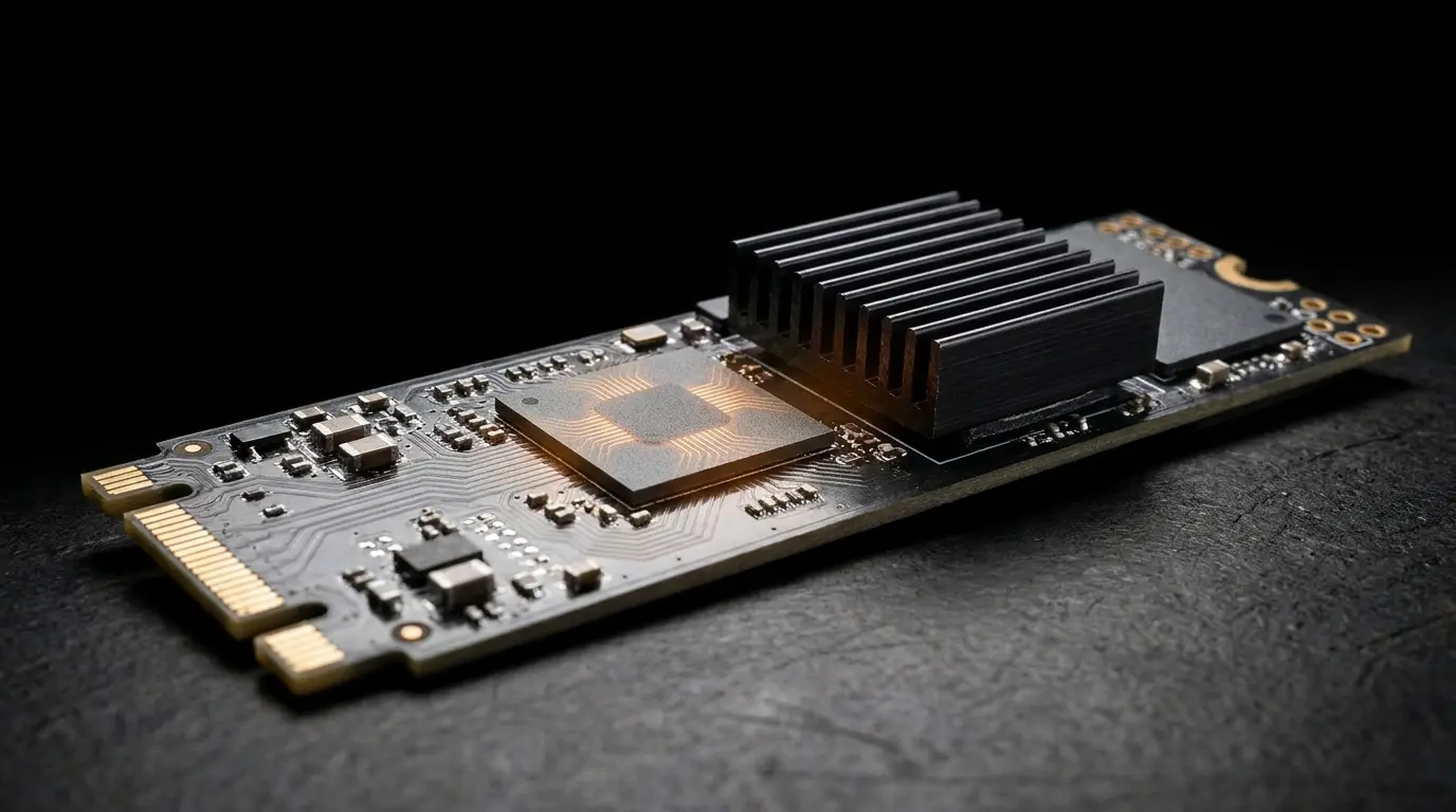
NVMe controller thermal throttling represents one of the most deceptive storage bottlenecks in modern high-throughput workstations and virtualization hypervisors, frequently masquerading as physical drive degradation or filesystem corruption. While synthetic benchmarks show sequential burst speeds exceeding 7,000 MB/s on PCIe 4.0 and 12,000 MB/s on PCIe 5.0 interfaces, sustained mixed write operations can abruptly plummet to a catastrophic 40–50 MB/s. This sudden throughput collapse is driven not by NAND cell wear, but by the onboard Application-Specific Integrated Circuit (ASIC) controller reaching its critical junction temperature thresholds, forcing immediate hardware-level clock gating, queue serialization, and operating system storage stack timeouts.
- Thermal Architecture: ASIC Controller vs. 3D NAND Flash
- Tracing StorNVMe Event ID 129 and Queue Timeouts
- Step 1: Extracting SMART Thermal Logs via Linux nvme-cli
- Step 2: Monitoring StorNVMe Latency via PowerShell
- Step 3: Adjusting Windows PCIe ASPM and Power Policies
- Step 4: Physical Heat Dissipation and Heatsink Mounting Pressure
- Step 5: Firmware Verification and APST Configuration
- Frequently Asked Questions
Thermal Architecture: ASIC Controller vs. 3D NAND Flash
Diagnosing thermal issues requires separating the physical dynamics of the flash controller from the underlying memory cells. 3D NAND flash operates efficiently and preserves data retention integrity at elevated operational temperatures between 40°C and 60°C; cold NAND writes actually accelerate gate oxide degradation. Conversely, the NVMe ASIC controller—housing multi-core ARM or proprietary RISC-V processors, PCIe PHY layers, and high-speed SRAM buffers—exhibits rapid switching losses under heavy random 4K queuing.
When the controller junction temperature breaches predefined register boundaries, the firmware enforces Thermal Management Temperature steps (TMT1 and TMT2) defined in the NVM Express base specification. Under TMT1, the controller issues duty-cycling to throttle clock cycles by 25–50%. If thermal dissipation remains inadequate and temperatures hit TMT2, the controller invokes aggressive failsafes: dropping the PCIe link speed (e.g., from Gen 5 to Gen 1), reducing link width (x4 to x1), or pausing the command parsing engine entirely.
| Telemetry State | Standard Temp Trigger | Controller Operational Behavior | Observed Throughput Impact |
|---|---|---|---|
| Normal Operation | < 70°C | Full link negotiation (PCIe x4), dynamic queue scheduling | 100% Rated Sequential/Random Specs |
| TMT1 (Light Throttling) | 72°C – 78°C | Clock frequency scaling, microsecond command delays | 25% – 45% Drop in Sustained Writes |
| TMT2 (Heavy Throttling) | 80°C – 85°C | PCIe link speed demotion, I/O queue command starvation | Throughput stalls down to 40–60 MB/s |
| Thermal Shutdown (Failsafe) | > 85°C | ASIC halts, PCIe disconnect, controller drop-out | Complete storage disconnection / BSOD |
Tracing StorNVMe Event ID 129 and Queue Timeouts
In Windows environments, extreme controller thermal throttling triggers severe driver-level anomalies. The native storage driver stornvme.sys maintains strict command timeout thresholds (typically 8–10 seconds per I/O burst). When an overheated controller stops serving the Submission Queue to lower core junction temperatures, the pending commands exceed latency limits.
This state produces system freezes, application timeouts, and the following entry in the Windows System Event Log:
Log Name:      System
Source:        stornvme
Event ID:      129
Level:         Warning
Description:   Reset to device, \Device\RaidPort0, was issued.
If the controller takes longer than the driver timeout threshold to recover its operational registers, the storage stack encounters an unrecoverable kernel panic, resulting in a system crash. For detailed kernel crash analysis and dump extraction procedures, consult our troubleshooting guide on resolving DPC_WATCHDOG_VIOLATION (Bug Check 0x133) storage exceptions.
Step 1: Extracting SMART Thermal Logs via Linux nvme-cli
Operating system sensor utilities often report a single blended temperature value, which usually reflects the relatively cool NAND flash while concealing an overheated controller ASIC. To obtain true junction telemetry, deploy the low-level nvme-cli utility suite:
# Install NVMe command-line tools
sudo apt-get install nvme-cli -y

# Query active SMART telemetry log pages
sudo nvme smart-log /dev/nvme0n1
Inspect the output specifically for temperature_sensor_1 (controller junction) versus temperature_sensor_2 (NAND substrate), as well as thermal management history:
temperature                         : 78°C (351 K)
Sensor 1                            : 84°C
Sensor 2                            : 52°C
Thermal Management T1 Trans Count   : 142
Thermal Management T2 Trans Count   : 29
Thermal Management T1 Total Time    : 00:14:22
Thermal Management T2 Total Time    : 00:03:05
If Thermal Management T2 Trans Count increments during your storage workloads, the controller is dropping into failsafe serialization mode. Detailed register field definitions are documented in the official NVM Express Base Specifications.
Step 2: Monitoring StorNVMe Latency via PowerShell
To identify whether your Windows environment is suffering from controller queue starvation, capture storage latency metrics directly from the performance counter subsystem using administrative PowerShell:
Get-Counter -Counter "\PhysicalDisk(*)\Avg. Disk sec/Write", "\PhysicalDisk(*)\Current Disk Queue Length" -Continuous -SampleInterval 1 |
ForEach-Object {
    $_.CounterSamples | Where-Object { $_.CookedValue -gt 0.05 -and $_.InstanceName -notmatch "_Total" } |
    Select-Object InstanceName, @{Name="Latency_MS";Expression={[math]::Round($_.CookedValue * 1000, 2)}}
}
Healthy PCIe NVMe write latencies hover between 0.02 ms and 0.2 ms under load. If latency metrics consistently jump above 50 ms to 500 ms while sequential write speed drops to 50 MB/s, thermal queue stalling is confirmed.
Step 3: Adjusting Windows PCIe ASPM and Power Policies
Aggressive link power state transitions can exacerbate thermal spikes due to continuous voltage step fluctuations in the controller PHY layer. To stabilize the PCIe power delivery profile, configure the storage subsystem via the Windows Registry:
# Disable PCIe Link State Power Management on the active power profile
powercfg /SETACVALUEINDEX SCHEME_CURRENT SUB_PCIEXPRESS ASPM 0
powercfg /SETACTIVE SCHEME_CURRENT
For systems managed under strict driver control, review the Microsoft StorNVMe Feature Support Guidelines to ensure that device firmware matches host driver features across production server nodes.
Step 4: Physical Heat Dissipation and Heatsink Mounting Pressure
Software adjustments cannot compensate for mechanical mounting failures. More than 80% of real-world NVMe controller overheating is caused by improper physical installation:
- Uneven Thermal Pad Contact: The controller die sits at a lower physical height (z-height) than the adjacent 3D NAND flash packages on many PCB layouts. Standard flat thermal pads often make firm contact with the NAND while leaving a microscopic air gap above the controller. Always use multi-thickness thermal pads (e.g., 1.5mm over the controller, 1.0mm over the NAND).
- Integrated Motherboard Shields: Thin stamped-aluminum decorative covers lack the mass required for PCIe 5.0 controllers drawing upwards of 11–14W under load. Replace passive covers with dedicated finned copper heatsinks featuring direct-contact heatpipes (such as the Crucial T700 with Heatsink).
- Chassis Boundary Layer Airflow: M.2 slots positioned directly beneath GPU backplates sit in static thermal pockets. Direct forced airflow across the slot area lowers controller junction temperatures by 15°C to 25°C under sustained load.
When engineering high-density storage arrays or testing sustained multi-gigabyte infrastructure pipelines, we validate sustained non-throttled I/O profiles across Storage & RAM diagnostics protocols and dedicated enterprise virtualization environments.
Step 5: Firmware Verification and APST Configuration
Modern SSD vendors issue firmware revisions specifically targeted at recalibrating thermal management tables. Query and verify your controller firmware revision using administrative PowerShell:
Get-PhysicalDisk | Where-Object BusType -eq "NVMe" | Select-Object FriendlyName, SerialNumber, FirmwareVersionUpdate the drive to the latest vendor firmware to ensure dynamic Autonomous Power State Transitions (APST) correctly regulate thermal dissipation without locking the queue scheduler.
Frequently Asked Questions
Why does write speed drop specifically to 50 MB/s instead of stopping completely?
When the controller reaches TMT2 thresholds, firmware failsafes enforce strict command serialization and clock gating. The controller halts parallel processing across multiple flash channels and processes write queues through a single fallback channel to limit thermal dissipation, resulting in legacy USB 2.0 / SATA fallback performance levels.
Does NVMe thermal throttling damage the SSD permanently?
Thermal throttling itself is a protection mechanism designed to prevent silicon failure. However, repeated thermal cycling between 40°C and 90°C can degrade the solder balls under the BGA package of the controller over time, leading to mechanical connection failure and permanent device loss.
Should I apply a thermal pad and heatsink to the NAND flash chips?
Yes, but with priority given to the controller. While NAND benefits from remaining at moderate operational temperatures (40°C to 60°C), cooling the controller ASIC down below 70°C is critical to avoid throughput throttling. Ensure the thermal pad makes firm physical contact with the controller die.
For homelabs, remote testing, and staging environments, we run NVMe VDS instances on Erahost. Fast provisioning, European routing, and predictable I/O.
View NVMe Plans →