

To Fix DDR5 Slow Boot cycles on modern desktop platforms, systems architects and performance enthusiasts must address the extensive hardware initialization procedures executed by the memory controller. Unlike legacy DDR4 topologies, high-speed DDR5 platforms—particularly AMD Socket AM5 (Ryzen 7000/9000 series) and Intel LGA1700/LGA1851 (Z790/Z890 chipsets)—frequently spend between 45 and 95 seconds in a pre-boot state known as DRAM training. During this phase, diagnostic motherboard debug LEDs typically stall on the yellow or orange DRAM indicator, or digital POST displays halt on Q-Codes 15, 00, or C5. When left unmanaged, this prolonged verification sequence triggers user-initiated hard resets, false hardware fault reports, and intermittent cold-boot boot loops.
- Why DDR5 Demands Extended Memory Training
- Comparison of DDR5 POST Optimization Parameters
- The Golden Rule: Synchronizing Memory Context Restore and Power Down
- Hardware Audit: Interrogating Installed DRAM Modules
- Step-by-Step Procedure to Fix DDR5 Slow Boot
- Hardware Specification Guidance for Zero-Training Workstations
- Frequently Asked Questions
Why DDR5 Demands Extended Memory Training
DDR5 memory transfers data at transfer rates scaling from 4800 MT/s to 6400 MT/s and beyond on consumer motherboards. At these high signal frequencies, electrical trace length variances of mere micrometers between CPU socket pins and dual in-line memory module (DIMM) traces induce significant phase drift, crosstalk, and impedance shifts. Furthermore, DDR5 shifts power regulation from the motherboard directly onto the module via an onboard Power Management Integrated Circuit (PMIC), operating separate VDD, VDDQ, and VPP rails.
Upon every cold boot or power-state transition, the motherboard UEFI/BIOS executes an extensive hardware loop that evaluates several critical physical layer parameters:
- Read/Write DQ Centering: Sweeping timing delay lines to place the data strobe (DQS) squarely in the center of the data eye.
- On-Die Termination (ODT) Calibration: Adjusting resistive termination to minimize signal reflections across high-speed bus lines.
- Decision Feedback Equalization (DFE): Compensating for inter-symbol interference on long motherboard traces.
- PMIC Rail Ramp Verification: Validating that onboard regulators provide stable 1.1V–1.4V current before handing off execution to the operating system kernel.
When motherboard firmware cannot locate a validated timing map within a specific cycle count, it repeats the calibration loop. If system firmware resets the trained profile on every boot, the system incurs the full 60-to-90-second delay indefinitely. For broader diagnostics on system stability and hardware crashes, consult our guide on analyzing BSOD via WinDbg.
Comparison of DDR5 POST Optimization Parameters
To eliminate redundant initialization without inducing operating system crashes, firmware vendors provide specific toggle registers inside the UEFI memory subsystem. The table below outlines their architectural function, recommended operational state, and stability impact:
| Firmware Parameter | Default State | Optimized Setting | Primary Subsystem Impact | System Stability Risk |
|---|---|---|---|---|
| Memory Context Restore (MCR) | Auto (Disabled) | Enabled | Skips full DRAM retraining; restores cached PHY parameters from CMOS/NVRAM. | High if toggled without Power Down Enable. |
| Power Down Enable (PDE) | Auto | Enabled | Keeps DRAM CKE lines synchronized when entering low-power sleep states. | None; mandatory pair for MCR on AM5. |
| Fast Boot (UEFI) | Enabled | Enabled | Bypasses polling of inactive USB, SATA, and auxiliary PCIe expansion slots. | Low; prevents direct DEL/F2 key intercept without OS reboot flag. |
| DRAM Frequency / EXPO Profile | JEDEC (4800 MT/s) | EXPO / XMP I (6000 MT/s) | Establishes factory-binned primary, secondary, and tertiary sub-timings. | Low on 2-DIMM configurations; High on 4-DIMM setups. |
The Golden Rule: Synchronizing Memory Context Restore and Power Down
The most common root cause of Blue Screen of Death (BSOD) crashes immediately following DDR5 optimization—such as MEMORY_MANAGEMENT (0x0000001A) or PAGE_FAULT_IN_NONPAGED_AREA (0x00000050)—is the isolated activation of Memory Context Restore without enabling Power Down Enable.
When Memory Context Restore is forced to Enabled, the memory controller reuses the previously stored signal calibration table upon power-up. However, if Power Down Enable remains disabled or set to Auto, the DRAM physical layer (PHY) drops clock enable signals during low-power C-states. This discrepancy leads to immediate timing desynchronization when the Windows kernel initializes the memory manager. According to the Microsoft Windows Hardware Error Architecture (WHEA) documentation, uncorrected bit flips during early NT kernel loading trigger instantaneous bug checks.
Engineering Directive: In your motherboard UEFI (ASUS, MSI, Gigabyte, or ASRock), never set Memory Context Restore to Enabled in isolation. Locate Power Down Enable (often found under Advanced DRAM Configuration or AMD CBS / UMC Common Options) and explicitly force both parameters to Enabled.
Hardware Audit: Interrogating Installed DRAM Modules
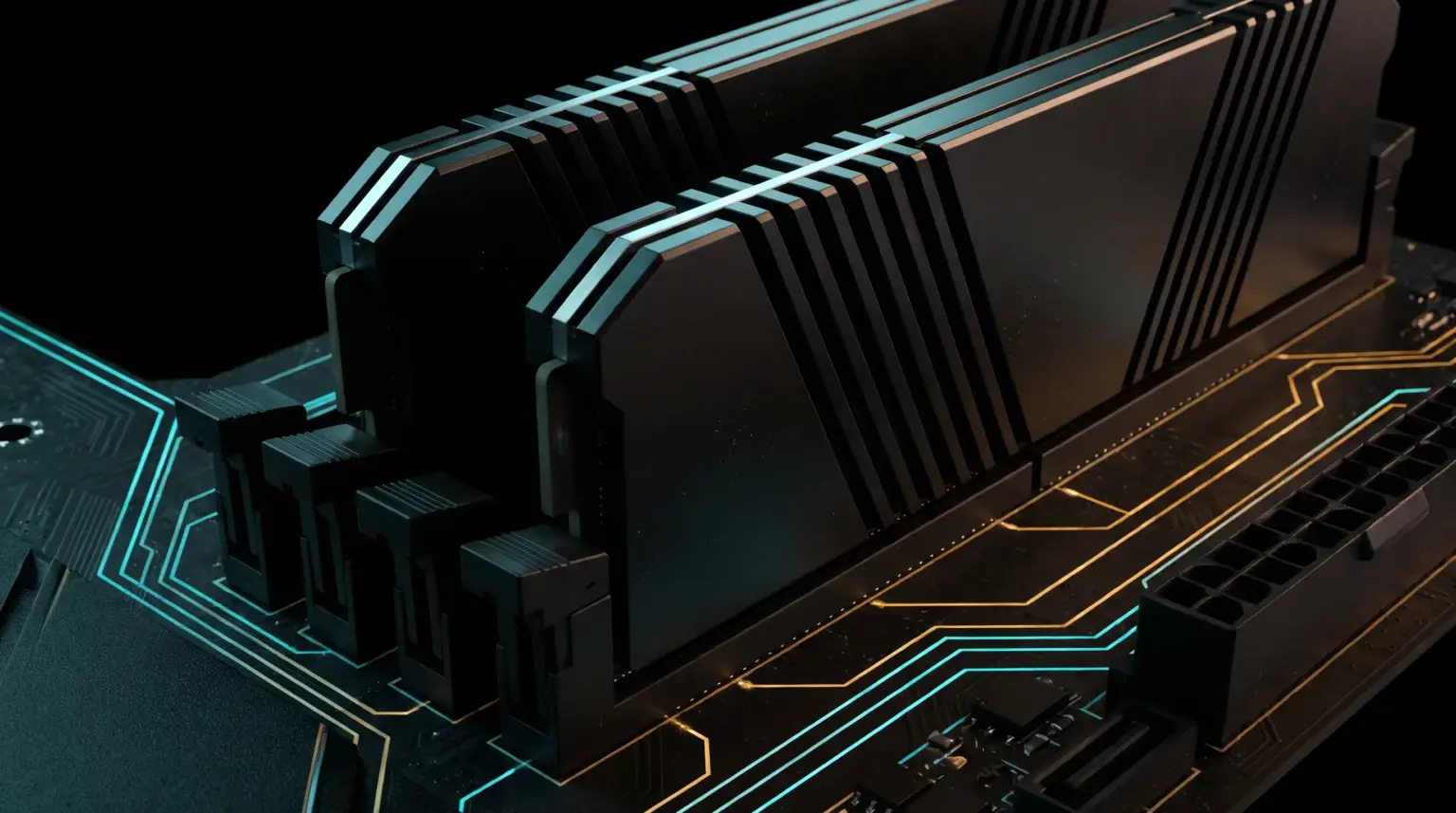
Before applying aggressive timing bypasses, verify that your modules operate under supported voltage and clock topologies. Running four dual-rank DDR5 modules on consumer platforms frequently forces memory controllers to step down to 3600–4400 MT/s to maintain electrical signal integrity. For optimal POST times and maximum throughput, dual-channel setups should leverage exactly two matched single-rank or dual-rank modules populated strictly in slots A2 and B2 (slots 2 and 4 from the CPU socket).
To inspect your current memory topology, manufacturer part numbers, and negotiated clock speeds without rebooting into UEFI, execute the following PowerShell command in an elevated console:
Get-CimInstance Win32_PhysicalMemory | Select-Object BankLabel, Capacity, Speed, ConfiguredClockSpeed, Manufacturer, PartNumber | Format-Table -AutoSizeOn Linux systems or hypervisors, extract physical slot assignments, serial numbers, and configured voltage levels using dmidecode:
sudo dmidecode --type 17 | grep -E 'Locator:|Speed:|Configured Memory Speed:|Manufacturer:|Part Number:|Configured Voltage:'Step-by-Step Procedure to Fix DDR5 Slow Boot
- Flash the Latest AGESA / Microcode UEFI: Motherboard manufacturers release frequent firmware updates specifically targeting DRAM training algorithms and PMIC handshakes. Ensure your BIOS includes the latest baseline microcode before adjusting registers.
- Clear CMOS and Load Baseline EXPO/XMP: Boot into UEFI, apply optimized defaults, and enable your certified memory profile (AMD EXPO or Intel XMP) targeting the platform sweet spot (DDR5-6000 CL30 for AM5; DDR5-6400 to 7200 for Intel Core 14th/15th Gen).
- Allow One Complete Training Cycle: Save and exit. Let the workstation execute a complete training sequence. The system may restart 2 to 3 times over 90–120 seconds. Do not interrupt power during this process.
- Lock MCR and Power Down Registers: Re-enter UEFI. Navigate to the Overclocking / AMD CBS / DRAM Timing section. Set both
Memory Context RestoreandPower Down Enableto Enabled. - Stabilize PMIC and SoC Voltages: If training loops persist intermittently, manually assign CPU VDDCR_SOC (AM5) to a fixed 1.20V (do not exceed 1.30V) and set DRAM VDD/VDDQ to their factory profile specifications (typically 1.35V for CL30 kits). Check our hardware taxonomy in Storage & RAM for platform-specific voltage tolerances.
Hardware Specification Guidance for Zero-Training Workstations
When designing high-reliability developer workstations and virtualized home labs, hardware selection determines cold-boot behavior. Prioritize memory kits equipped with SK Hynix A-die or M-die integrated circuits over older Samsung B-die DDR5 variants, as Hynix silicon achieves stable impedance training significantly faster under identical signal loads. For predictable POST delays and instant MCR stability on AM5 and Intel platforms, low-latency kits such as the Kingston FURY Beast 32GB (2x16GB) 6000MT/s DDR5 CL30 provide verified EXPO/XMP profiles with factory-tuned termination impedances.
Ensure that modules include an integrated thermal sensor reporting directly through the PMIC to the SMBus, accompanied by an aluminum heat spreader with functional thermal pads over the PMIC itself. Elevated PMIC operating temperatures (exceeding 65°C under sustained load) cause voltage drift that triggers retraining routines upon subsequent reboots.
Frequently Asked Questions
Why did my PC take 2 minutes to boot after updating the BIOS?
A BIOS flash wipes the non-volatile memory (NVRAM) containing the previous electrical calibration table. The memory controller is forced to run a full, cold-state training sequence across every trace to map clock skews and signal eyes from scratch.
Can enabling Memory Context Restore cause data corruption?
Not if memory timings are electrically stable. However, if your system memory is marginally unstable under an aggressive overclock, bypassing boot training prevents the system from adapting to ambient temperature changes, which can lead to random memory bit errors over time.
Why does my motherboard refuse to POST with 4 sticks of DDR5 at 6000 MT/s?
Consumer dual-channel memory controllers face high capacitive trace loading when two DIMMs share a single electrical channel (2DPC). Current memory controllers generally cannot maintain signal integrity above 4400–4800 MT/s with four dual-rank modules installed without extensive manual sub-timing relaxation and voltage increases.
For homelabs, remote testing, and staging environments, we run NVMe VDS instances on Erahost. Fast provisioning, European routing, and predictable I/O.
View NVMe Plans →