

A broken twisted pair in an inter-floor riser or distribution cabinet is one of the most frustrating emergencies faced by a network engineer or a last-mile installer. The situation becomes even more complicated when the main multi-pair cable runs out of spare wires, and pulling a new cable route between building entrances at the end of the working day is physically impossible. Let’s break down a proven field case: how to localize the damage using a professional cable scanner and quickly restore the network for the subscriber using a compact switch without laying any new cables.
Symptoms of Failure: Speed Drops and Lost Links
In standard data networks operating at 100 Mbps (100BASE-TX standard), two twisted pairs (4 wires) are utilized for signal transmission: pins 1-2 (TX) and pins 3-6 (RX). If a broken twisted pair occurs in at least one wire out of these essential pairs, the network adapter will either completely lose the link or auto-negotiate the connection down to the legacy 10BASE-T standard (speed capped at 10 Mbps). This hardware fallback inevitably leads to constant session drops, high latency, and immediate subscriber complaints about non-working internet access.
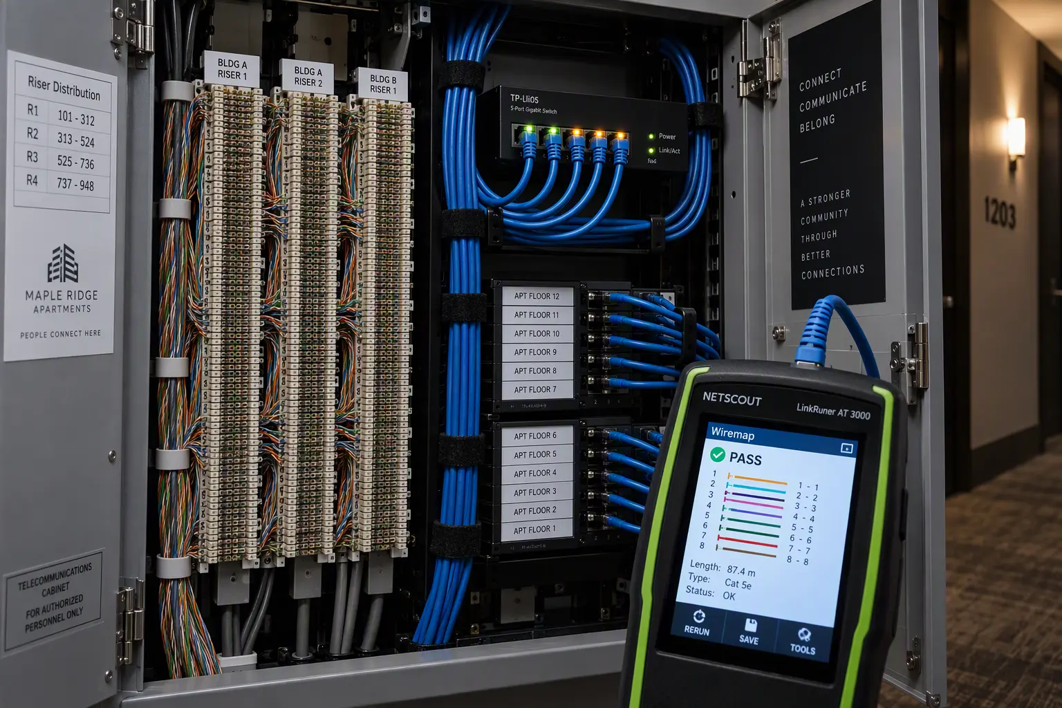
To perform a rapid and accurate diagnosis of the physical layer (L1), an engineer requires a specialized cable tester, such as the NetScout LinkRunner reflectometer. This type of equipment accurately determines the exact length of the conductors, identifies crosstalk, and pinpoints the exact location of the severed wires.
Broken Twisted Pair: Step-by-Step Fault Localization
When troubleshooting the physical link, it is critically important to sequentially divide the subscriber’s line into independent, testable segments:
- Client-Side Verification: Connect the scanner to the subscriber’s cable inside the apartment, and place a terminator (loopback plug) in the floor cabinet’s punch-down block. If all pairs ring out without breaks and the resistance is within normal limits, the indoor cable is completely intact.
- Inter-Floor Riser Diagnosis: Connect the tester to the specific pair leading from the cabinet’s punch-down blocks toward the main access switch. If the device confirms a broken twisted pair at a specific meterage (e.g., on contacts 3-6), the physical damage is located deep inside the inter-floor riser.
- Spare Wire Check: Telecommunication cabinets often utilize a 25-pair cable (multi-pair Cat3/Cat5). If all backup pairs in the block are already occupied by other active subscribers or suffer from short circuits, the standard method of “switching to a spare pair” simply will not work.
Field Solution: L2 Segment Extension via a 5-Port Switch
When laying a completely new backbone line is impossible, localizing the switching segment directly in the distribution cabinet where the broken twisted pair was detected is the best workaround:
1. Hardware Requirements
- A compact 5-port unmanaged Gigabit switch (often referred to as a “soapbox”).
- An internal 220V power socket inside the telecom cabinet to power the device.
- Standard Cat5e patch cords terminated with RJ-45 connectors.
2. Switching Scheme
- Locate a neighboring subscriber connected via a Gigabit data plan (1000BASE-T) on the cross-panel. For this tier, all 4 twisted pairs (8 wires) are routed from the main switch to the cabinet.
- Disconnect the wires of this Gigabit subscriber from the punch-down block and crimp them into an RJ-45 connector (or use a dedicated keystone adapter).
- Insert this newly crimped patch cord into the first port of the installed 5-port switch — this line now serves as the main Uplink to the provider.
- Plug the Gigabit neighbor’s local line into the second port of the switch.
- Plug the apartment cable of the problematic subscriber, who suffered the broken twisted pair, into the third port.
As a result, the ISP’s core access switch treats the port as a standard trunk link, while the local unmanaged switch distributes Ethernet frames between both subscribers at the L2 data link layer without any noticeable drop in bandwidth.
Stability Testing and Verification
After completing the wiring and applying power, always perform a final quality check. Run a continuous ping test to the ISP’s gateway using an increased packet size (ping -t -l 1472 gateway_IP) to ensure there is absolutely no packet loss and to confirm stable Full Duplex operation across all active ports.
Pitfalls and ISP Network Limitations
Before implementing this emergency connection scheme, you must consider the provider’s specific network configuration:
- Port Security (MAC Address Limits): If the core switch port has a strict
switchport port-security maximum 1rule configured, the appearance of a second MAC address will force the port into anerr-disablestate. This scheme only works with dynamic learning or a limit of at least 2 MAC addresses. - Subscriber Authorization: When using IPoE tied to a physical port (DHCP Option 82), both subscribers will now appear on the same logical port of the access switch. If the billing system strictly binds the IP to the port, a temporary adjustment in the admin panel will be required. With PPPoE authorization, no issues arise — PPPoE sessions are established independently.
- Cable Labeling: You must attach cable tags to the temporary patch cords and leave a clear note in the incident log so the next maintenance crew does not accidentally disconnect the “unknown switch”.
For more practical guides on hardware diagnostics and routing, read the Network & RDP section on the SoftAndGadget blog.
For homelabs, remote testing, and staging environments, we run NVMe VDS instances on Erahost. Fast provisioning, European routing, and predictable I/O.
View NVMe Plans →